
SEISMIC TESTS FOR DETERMINATION OF VP AND VS
Seismic Refraction Method.
The seismic refraction method is a geophysical technique widely used to determine the propagation speed of compressional seismic waves in the subsurface (Vp), which allows characterizing geological layers and subsurface structures. This method is valuable for geotechnical engineering, natural resource exploration, construction project planning, and land ripability.
Working Principle:
The seismic refraction method is based on the time it takes for seismic waves to travel from a seismic source on the surface to receivers or geophones located at different distances along a seismic line or line. The variation of wave propagation velocities in different layers of the subsurface is used to infer geological features.
Procedure
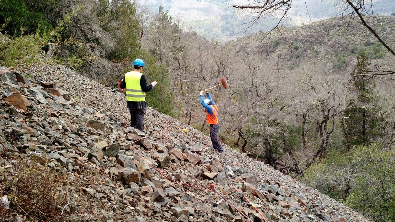
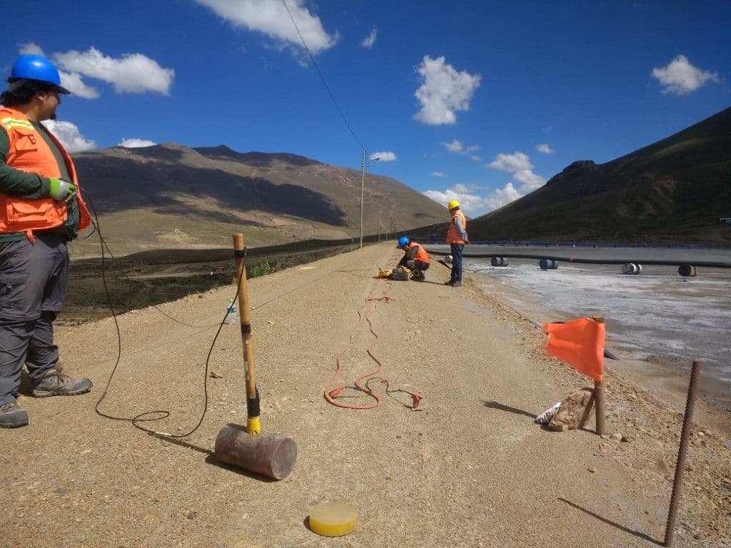
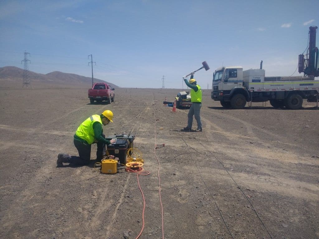
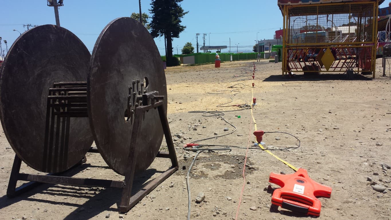
- Seismic Source: A seismic source, such as a hammer or a controlled explosion, is generated on the surface. Seismic waves travel through the ground and are refracted when they encounter different geological layers.
- Seismic Receivers: Geophones are usually installed at 4.5 Hz or 14 Hz natural frequency or other seismic receivers at different distances from the seismic source.
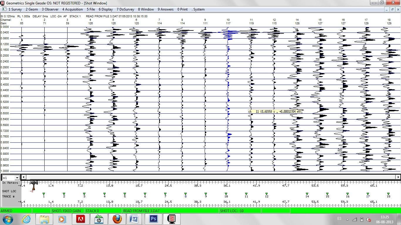
- Data Logging: The seismic waves generated by the seismic source reach the receivers at different times, which is recorded as arrival times. These times are used to calculate the propagation velocities of the waves in the different layers of the subsurface.
- Analysis and Interpretation: By analyzing arrival times and refraction curves, a subsurface velocity model is constructed. This model helps identify geological layers, interfaces, and subsurface structures.
Advantages
- Depth Resolution: Provides information about the properties of the subsurface at different depths.
- Determination of Velocities: It allows estimating the velocities of propagation of waves in the subsoil, which is essential for modeling the geological structure.
- Interface Identification: It is useful for identifying geological layers, such as strata, aquifers, and underground structures.
MASW Method (Multi-Channel Analysis of Surface Waves).
The MASW (Multi-Channel Analysis of Surface Waves) method is a state-of-the-art geophysical technique used to characterize the mechanical and structural properties of the subsurface, especially in surface layers. This method is widely applied in geotechnical engineering, natural resource exploration, and the evaluation of ground seismic response. It also allows you to determine the Vs30 parameter, usually required by standard for constructions in general.
Working Principle:
The MASW method is based on the analysis of surface waves propagating along the interface between soil and air (or water). These surface waves, also known as Rayleigh waves, contain information about the speed of propagation and attenuation in the subsurface.
Procedure
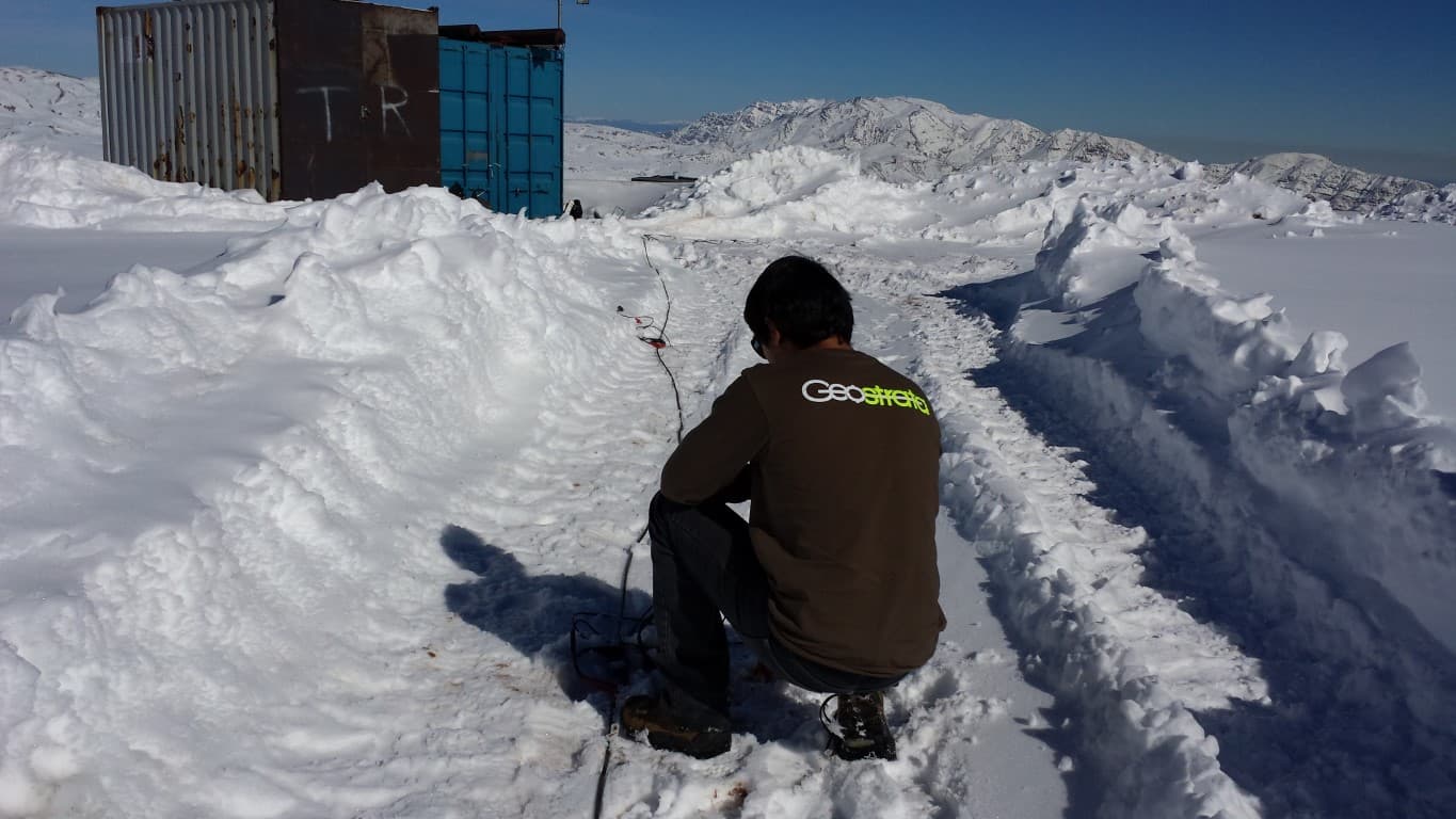
- Data Acquisition: A series of 4.5 Hz natural frequency geophones are placed on the ground surface in a linear arrangement or similar arrangement. These geophones record surface waves generated by a seismic source, such as a hammer or a blow.
- Signal Logging: Seismic signals received by geophones are recorded as surface waves travel through the subsurface.
- Scattering Analysis: From the recorded data, the frequency spectrum is calculated and a scattering analysis is performed to identify the phase velocities of the surface waves at different frequencies.
- Subsurface Modeling: Using inversion techniques, a wave propagation velocity profile is constructed in the subsurface. This profile can help identify geological layers and mechanical properties of the soil.
Advantages
- Shallow Depth: Focuses on the surface layers of the subsurface, which is useful for geotechnical engineering studies and seismic analysis.
- Mechanical Characterization: Provides information on soil stiffness and elasticity, which is crucial for construction planning and seismic risk assessment.
- Non-Invasive: Does not require significant disturbance on the ground and is well suited to urban and sensitive environments.
- High Resolution: Allows high spatial resolution to detect subtle changes in subsurface properties.
MAM Method (Microtremor Array Measurements).
The MAM (Microtremor Array Measurements) method is a geophysical technique that takes advantage of natural ground vibrations, known as microtremors, to investigate the properties of the subsoil. This approach is especially valuable for the characterization of sediments and surface soils, as well as for the evaluation of local seismic response.
Working Principle:
The MAM method is based on the analysis of natural ground vibrations caused by environmental sources such as traffic, wind and human activities. These vibrations generate surface waves that can be used to obtain information about the structure and geotechnical properties of the subsurface.
REMI Method (Refraction Microtremor).
The REMI (Refraction Microtremor) method is a geophysical technique that combines the principles of seismic refraction and natural ground vibrations (microtremors), it is similar to the MAM method. It is used to map the propagation speed of surface waves and determine the geotechnical and structural properties of the subsurface at surface levels.
Working Principle:
The REMI method is based on the analysis of surface waves generated by environmental microtremors. These surface waves are influenced by subsurface properties and can be used to infer wave propagation velocity and local seismic response.
Procedure
- Sensor Distribution: An array of sensors, such as geophones or accelerometers, is installed on the surface of the ground in a linear or circular array.
- Microtremores Logging: Sensors record the natural vibrations of the ground (microtremores) over a period of time. Usually for the MAM, geophones of 4.5 Hz of natural frequency and 2 Hz for the REMI are used. These signals are used to calculate soil properties and subsurface structure.
- Spectral Analysis: The frequency spectrum of the recorded microtremor signals is calculated to identify the natural resonance frequencies of the soil and the characteristics of the geological layers.
- Inversion and Modeling: Using inversion techniques, a subsurface profile is constructed that shows wave propagation velocities and geotechnical properties at different depths.
Advantages
- Natural Vibrations: Harnesses natural ground vibrations, minimizing the need for controlled seismic sources.
- Surface Characterization: It is effective for the characterization of surface soils and sediments, as well as for the evaluation of the local seismic response.
- Non-Invasive: It does not require the generation of additional seismic waves and is suitable for urban and sensitive environments.
- Resource Economy: Requires less equipment and time compared to traditional methods.
- Exploration depth: Both the MAM and REMI methods allow a wide range of depth to be obtained in the investigation of the subsoil by obtaining the Vs. parameter. Usually with the MAM method you can obtain up to 80 m deep and with the REMI even 200 m deep.
H/V Method or Nakamura.
The H/V method, also known as the Nakamura method or the H/V Nakamura method, is an advanced geophysical technique used to investigate the structural properties of the subsurface in a non-invasive manner. This method has become an essential tool in site characterization for a variety of applications, such as geotechnical engineering, seismology, seismic risk assessment, and infrastructure planning.
Working Principle:
The H/V method is based on the analysis of ambient microtremor waves, which are natural vibrations of the ground caused by sources such as traffic, wind or human activities. These vibrations are captured by surface seismic stations and processed to extract valuable information about the properties of the subsurface.
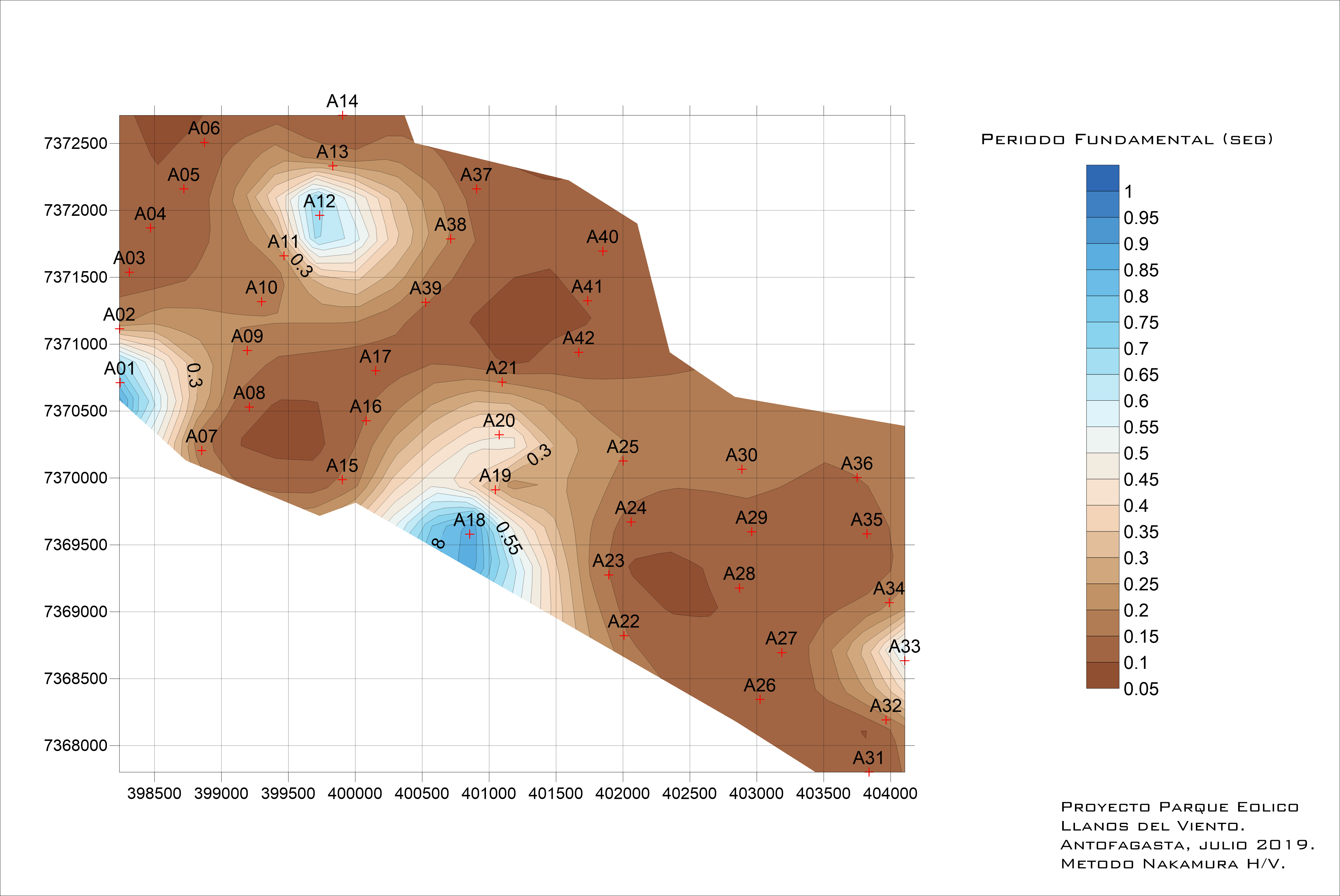
Procedure
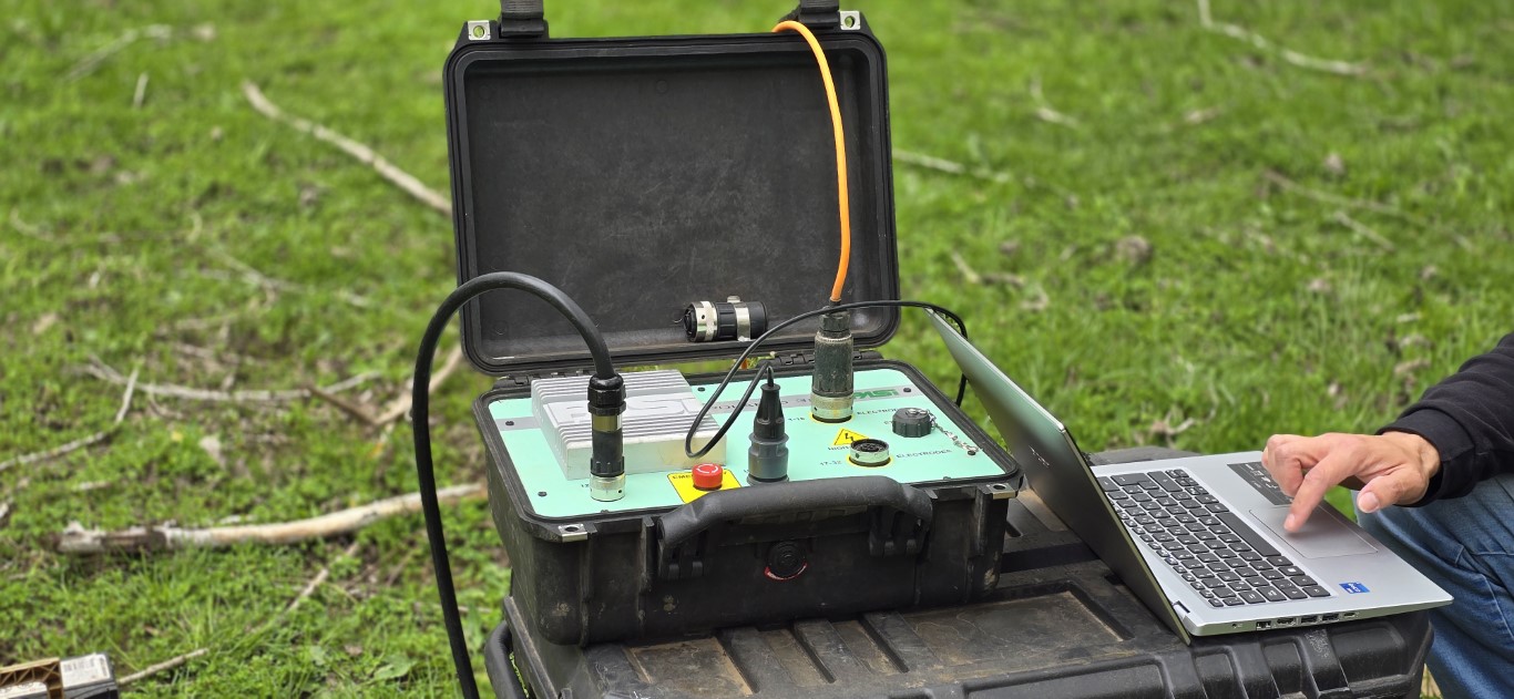
- Data Acquisition: Seismic sensors are installed on the ground surface to measure the natural vibrations of the ground over a period of time.
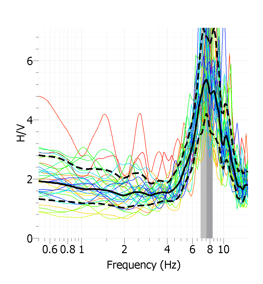
- Spectral Analysis: Spectral analysis is applied to the recorded data to calculate the amplitude-frequency spectrum of vibrations. The spectrum reveals the dominant frequencies present in the microtremor waves.
- H/V ratio: The ratio between the amplitudes of the horizontal and vertical component of the spectrum (H/V) is calculated. This relationship is sensitive to the properties of the subsurface and to the resonance characteristics present at the site.
- Interpretation: The H/V ratio is compared with theoretical models and previous databases to infer the characteristics of the subsoil. Peaks in the H/V spectrum can indicate the presence of geological layers, stiffness interfaces, and potential seismic amplification zones.
Advantages
- Non-invasive: The H/V method uses natural ground vibrations and does not require controlled energy sources.
- Low interference: Can be performed in urban and populated environments without causing significant disturbance.
- Fast and efficient: The measurement and analysis process is relatively fast, allowing preliminary results to be obtained in a short time.
- Detailed Information: Provides information on the mechanical and structural properties of the subsurface, which is critical for infrastructure planning and seismic risk assessment.
ELECTRICAL RESISTIVITY TESTS
High Density Electrical Resistivity Tomography (ERT) Method.
High-Density Electrical Resistivity Tomography is a state-of-the-art geophysical technique that allows you to map variations in the electrical resistivity of the subsurface in a detailed and in-depth manner. This method is widely used in a variety of applications, from natural resource exploration to geotechnical engineering and aquifer characterization.
Working Principle:
The principle behind Electrical Resistivity Tomography (ERT) is based on the variation in electrical resistivity of different materials in the subsurface. An electric current is sent across the ground using surface electrodes and the resulting potential differences are measured. These measurements are used to calculate the apparent resistivity in different locations and by means of physical-mathematical algorithms it is possible to obtain 2D and/or 3D inversion models of the subsurface.
Procedure
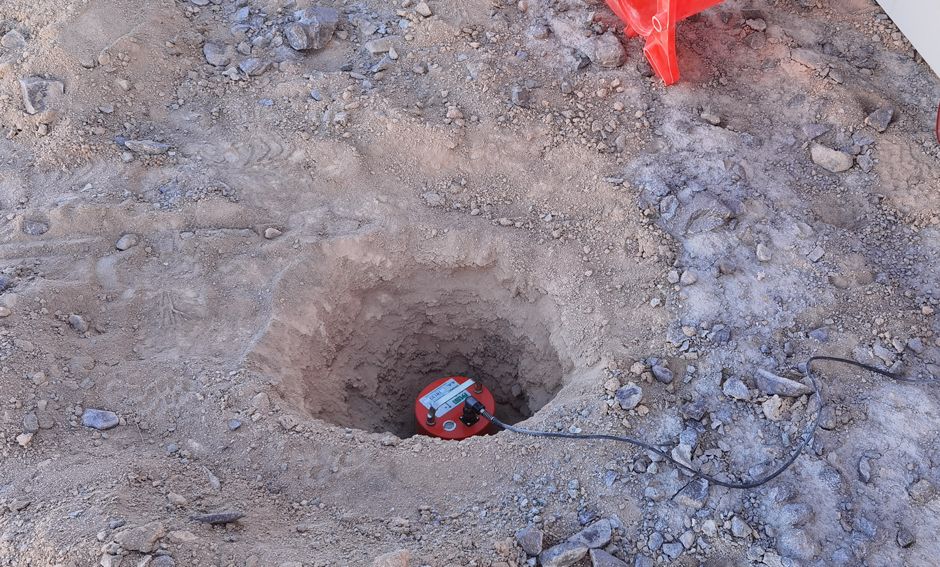
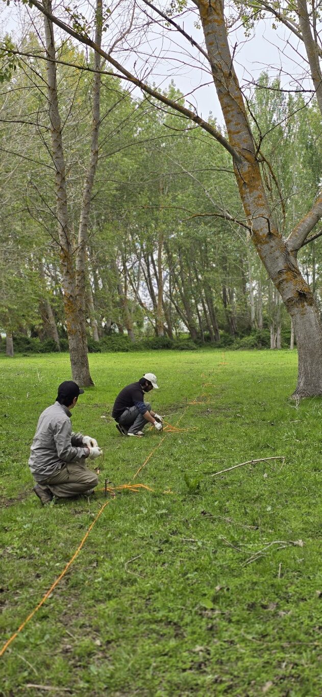
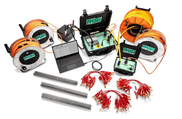
- Electrode Distribution Design: Electrodes are placed on the ground surface in a specific arrangement, forming a network of electrodes. For High Density Tomography, a larger number of electrodes is used to obtain a higher resolution.
- Current Injection: An electric current is injected through one pair of electrodes, and potential differences are recorded in other pairs of electrodes.
- Potential Measurements: Potential measurements are taken at different locations along the surface of the ground.
- Inversion and Reconstruction: Using inversion algorithms, the measurements are processed to obtain a distribution model of electrical resistivity in the subsurface. A three-dimensional image is generated that shows the variations in resistivity.
Advantages
- Spatial Resolution: The use of a higher density of electrodes provides a higher spatial resolution, which allows smaller structures and heterogeneities to be detected in the subsurface.
- Non-Invasive: TRE is a non-invasive method that does not require significant disturbance on the ground, making it suitable for urban and sensitive environments.
- Versatility: Can be applied in a variety of contexts, from mineral resource exploration to aquifer identification and structural integrity assessment.
- Three-Dimensional Information: Provides a three-dimensional representation of variations in electrical resistivity, aiding in the understanding of subsurface structure.
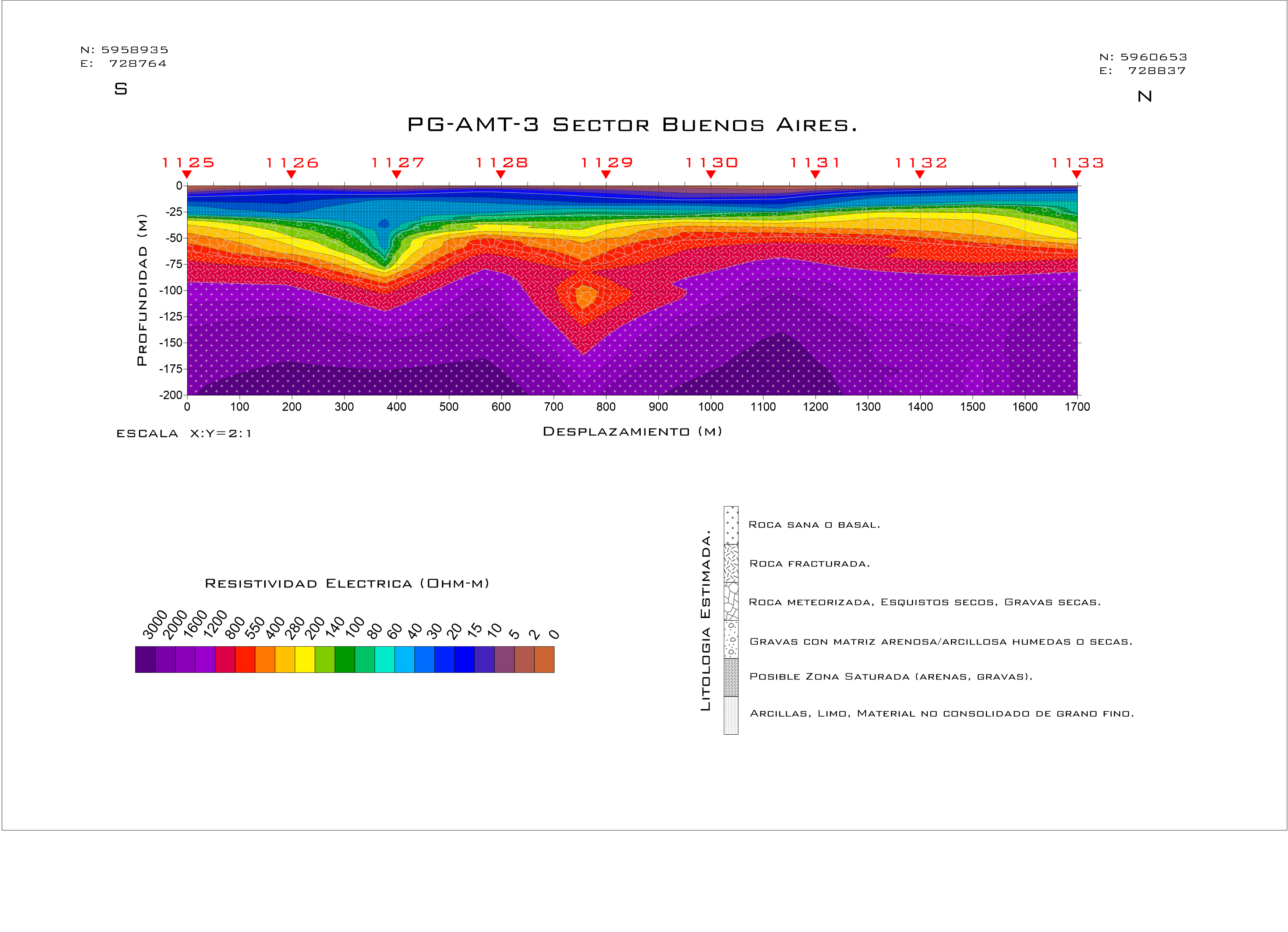
Audio-Magnetotelluric Method
The Audio-Magnetotelluric (AMT) method is an advanced geophysical technique used to investigate the electrical resistivity of the subsurface at different depths, from surface to even 1000 m depth. This method combines electrical and magnetic natural field measurements to obtain information about the resistivity distribution in the subsurface and to characterize geological and geotechnical properties.
Working Principle:
The AMT method is based on the detection of natural electromagnetic fields generated by cosmic and terrestrial sources. These fields change with the electrical resistivity of the subsurface, which allows inferring geological characteristics and soil properties.
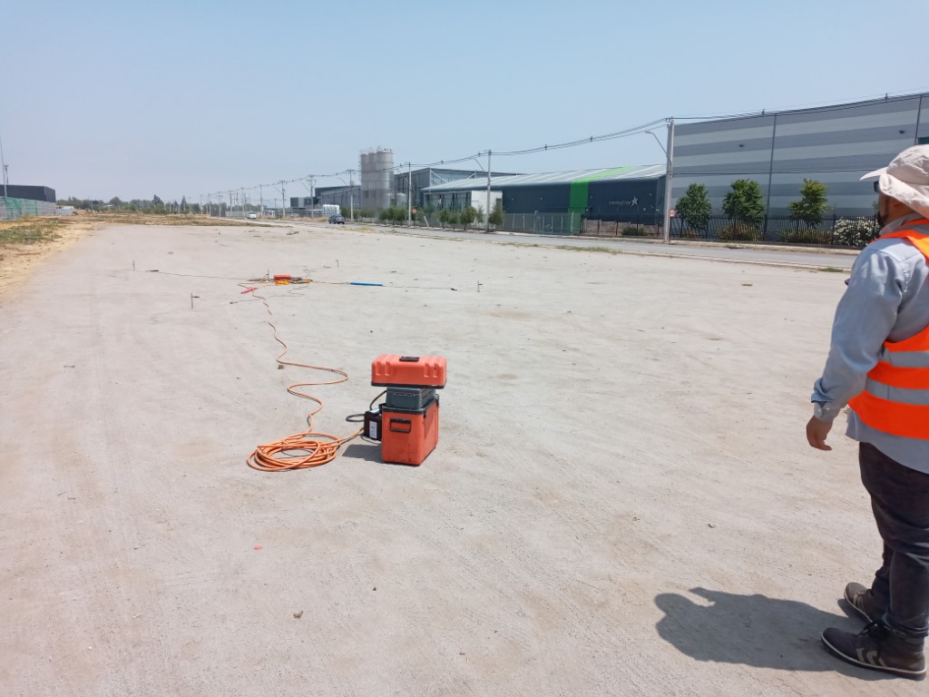
Procedure
- Sensor Distribution: Electrical (electrodes) and magnetic (magnetometers) sensors are installed on the ground surface in a suitable configuration.
- Data Logging: The sensors record extremely low frequency (VLF) and audio frequency (AM) electric and magnetic fields. These fields are influenced by the resistivity of the subsurface.
- Spectral Analysis: A spectral analysis of the recorded measurements is performed to calculate the electromagnetic response of the subsurface at different frequencies.
- Inversion and Modeling: Through inversion techniques, a three-dimensional profile of electrical resistivity in the subsurface is constructed, which allows characterizing the geological layers and geotechnical properties.
Advantages
- Depth and Resolution: Provides information on electrical resistivity at different depths, which is useful for natural resource exploration and geotechnical characterization.
- Complete Information: Combines electrical and magnetic measurements to obtain a complete picture of subsurface properties.
- Non-Invasive: Uses natural electromagnetic fields and does not require significant ground disturbance.
- Wide Range of Applications: Can be applied in a variety of contexts, from mineral resource searching to aquifer evaluation.
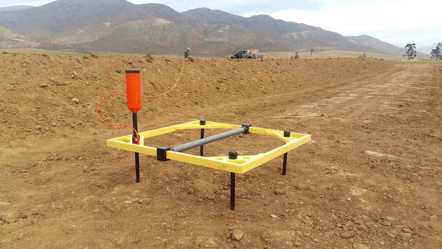
Transient Electromagnetic Method (TEM)
The Transient Electromagnetic Method (TEM) is an advanced, non-invasive geophysical technique used to investigate the vertical electrical resistivity distribution of the subsurface. Its main objective is to obtain information about the electrical and geological properties of subsurface layers. The TEM method is usually used in water resources exploration, geological characterization, detection of mineralized zones and identification of potential groundwater accumulation zones.
Working Principle:
The TEM method is based on the principle of electromagnetic induction, which consists of the generation of high intensity electric current pulses through an emitting coil placed on the ground surface. Subsequently, the pulse is stopped and the response time of the subsoil to return to its equilibrium state is measured by means of a receiver coil. These pulses generate electromagnetic fields that penetrate the subsurface and, as these fields change over time, induce electrical currents in the underlying geological formations, which allows determining the electrical resistivity of the subsurface.

Procedure
- Pulse Generation: A pulse of high intensity electric current is applied through the excitation coil at the surface. The current is abruptly interrupted, which causes a rapid variation in the electromagnetic field.
- Response Recording: The receiving coil or antennas record the electromagnetic response emitted by the subsurface as a function of time after the pulse interruption. These recorded signals contain information about the resistivity and geometry of the subsurface.
- Data Analysis: The relationship between the recorded signal and the time elapsed since the interruption of the pulse is analyzed. Through this analysis, different geological layers and structures can be identified based on how the signal changes with time.
- Inversion and Modeling: Using inversion techniques, a three-dimensional model of electrical resistivity in the subsurface is developed. This model provides information on the distribution of layers and the geometry of geological formations.
Advantages
- Depth and Resolution: Provides information on electrical resistivity at different depths, usually from surface to several hundred meters depth, which is directly proportional to the dimensions of the current emission loop used.
- Groundwater Detection: Allows the inference of groundwater accumulation zones and aquifers, by measuring the electrical resistivity parameter.
- Geological Information: Helps to identify geological layers, structures and discontinuities.
- Non-Invasive: No significant ground disturbance, no stakes, no use of controlled energy sources.
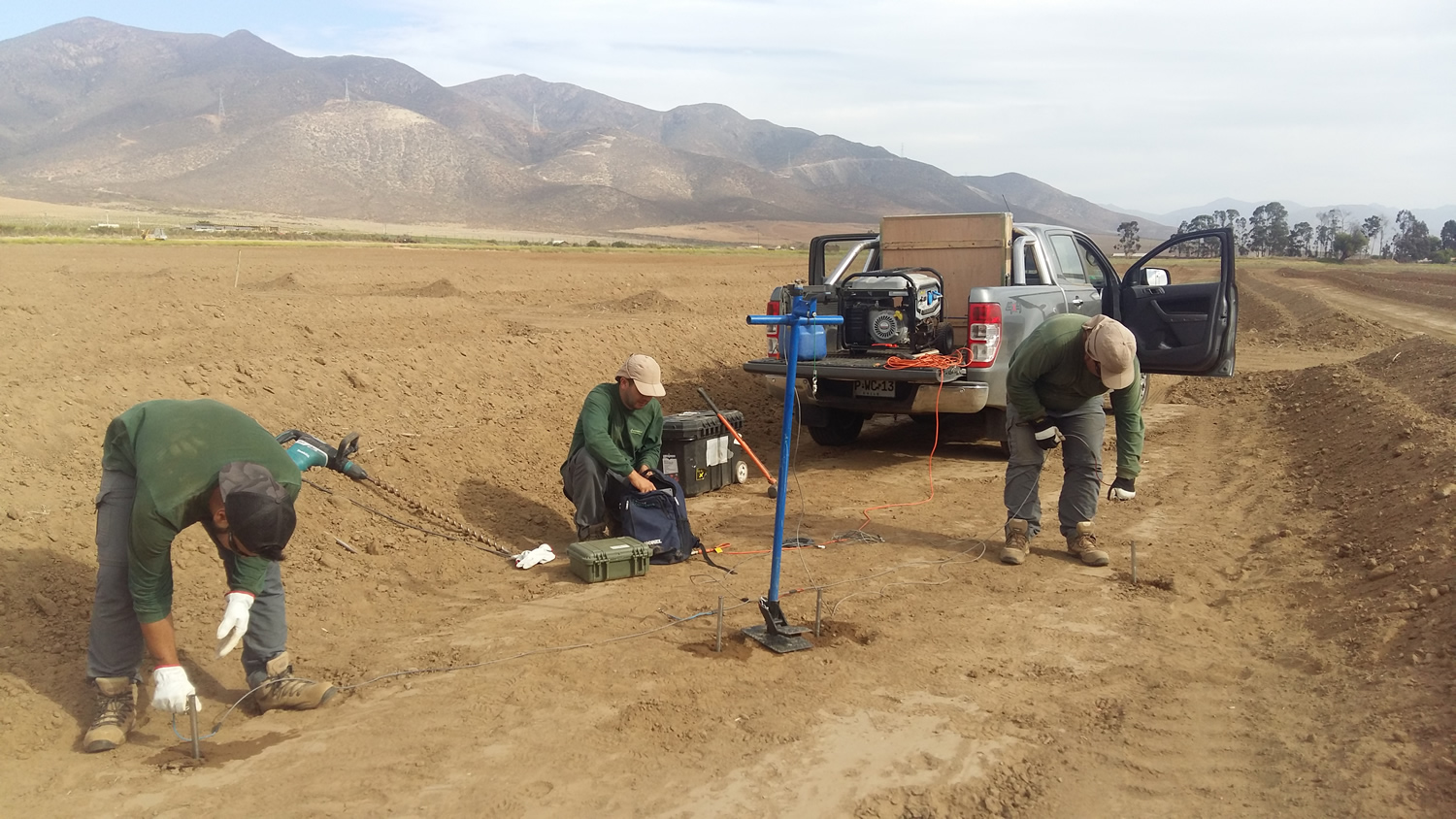
HYDRAULIC CONDUCTIVITY TESTS
Seismoelectric Method
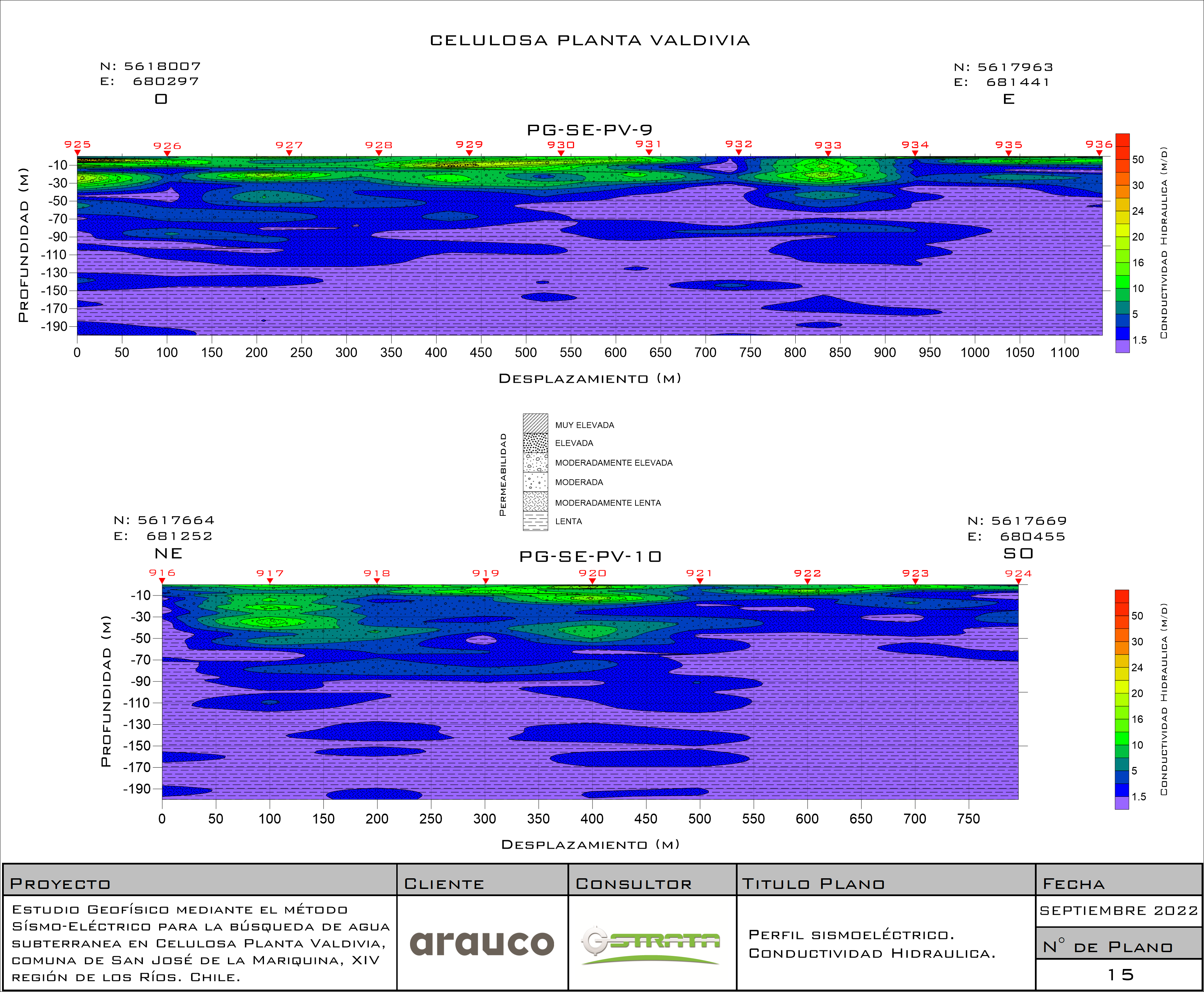
Seismoelectric testing is an advanced geophysical technique that combines principles of seismic and electrical methods to investigate the hydraulic properties of the subsurface in a comprehensive manner. This method is used to obtain valuable information about the presence or occurrence of subsurface water, being especially useful in applications related to water resources exploration and aquifer characterization.
Working Principle:
The seismoelectric test is based on the interaction between the seismic waves generated by a controlled surface seismic source, such as the blow of a sledgehammer or the detonation of an explosive charge, and the electrical response in the subsoil resulting from the passage of acoustic waves. The propagation of seismic waves induces variations in the electrical resistivity of materials, especially if water is present, and these variations are recorded through electrical measurements at the surface. The working mode of this method is to perform soundings in different places over the area to be evaluated, with which 2D and/or 3D models of the variation of the hydraulic conductivity of the subsoil can be obtained. It is also possible to estimate the flow rate of water inflows identified at depth. This technique allows to explore up to 200 m depth.
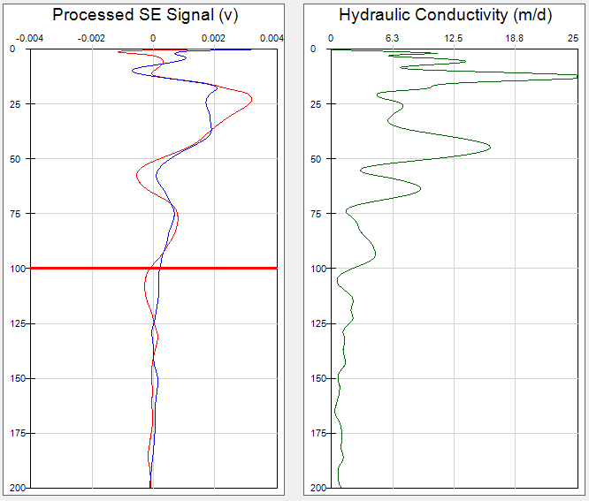
Procedure
- Seismic Source: A seismic source is generated at the surface by controlled shocks or hammers. The seismic waves travel through the ground and cause changes in the resistivity distribution.
- Measurement Electrodes: Electrodes are placed on the surface and possibly in boreholes or boreholes to measure variations in electrical potential induced by seismic waves.
- Data Recording:During and after the seismic source, electrical potential differences at the electrodes are recorded. These data are used to analyze how the seismic waves affect the electrical resistivity of the subsurface.
- Inversion and Analysis: Through inversion techniques, electrical and seismic data are processed to obtain a three-dimensional model of the resistivity distribution. This model can help identify zones with changes in fluid saturation and geologic features.
Advantages
- Integrated Characterization: Combines seismic and electrical information to provide a complete picture of subsurface properties.
- Fluid Detection:It is especially effective in detecting changes in water saturation, which is essential for aquifer exploration and water resource management.
- Non-invasive: Does not require the introduction of significant substances or disturbances into the ground, which minimizes environmental impact.
- Varied Applications:Can be applied in a variety of situations, from groundwater exploration to characterization of geologic formations.